Fire Mode, Economical Firing Mode-Single Phase SCR Power Controller-Advanced Energy-Fastron Electronics Store")


Fastron - Oztherm Power Controller F330 Series Calibration Procedure
Fastron - Oztherm Power Controller F330 Series Calibration Procedure
In this article we discuss the calibration procedure for F330 Series Single Phase Thyristor (SCR) Controllers.
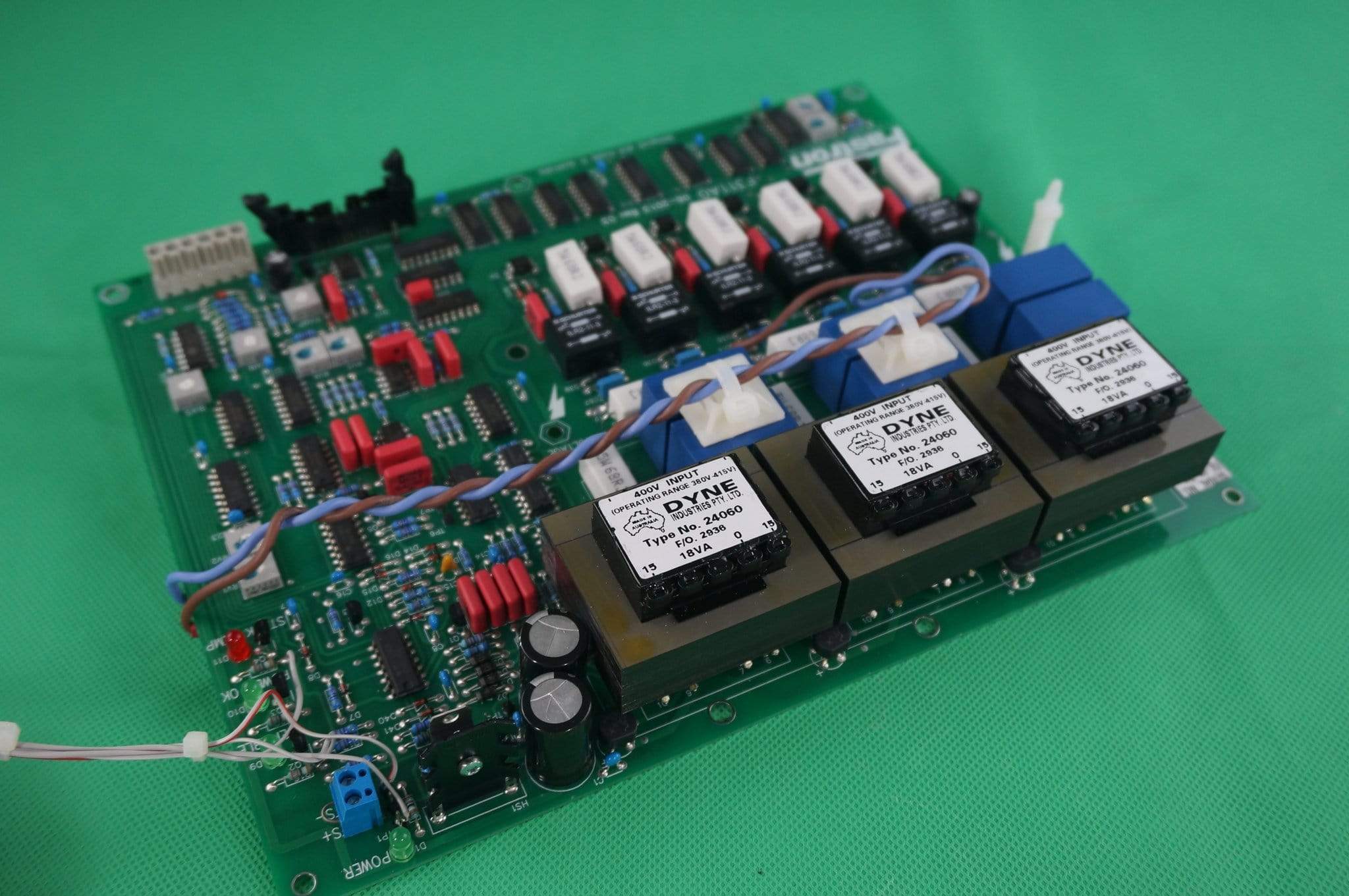
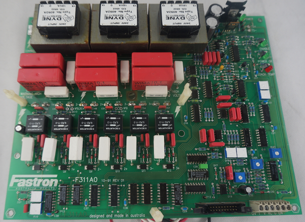
PCB F311AO(Firing Card)
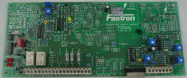
F311A1 (Option Card)
Please refer to the F330 installation and commissioning manual for detailed wiring connection instructions.
Wiring diagrams for various applications;
- Standard Thyristor Wiring Diagram
- Control Card Wiring Diagram F311A1
- New CCE option PCB1019-XX Wiring Diagram
- Bridge Output Thyristor Wiring Diagram
- Primary Transformer Wiring Diagram
- Start Delta Wiring Diagram
Controller Identification
F330 Controllers are fitted with a single PCB marked F321A0 and F311A1. There should be a silver sticker on the PCB with a serial number in the format of YY-MM-Serial #
Controller Options Identification
There are various options available for this controller which the most common are listed and indicated by the following nomenclature
- (FW) - Four Wire Load (Neutral) Critical for applications with return neutral currents
- (A) - A.C. Voltage Regulation
- (C) - Current Limit and Trip
- (CC) - Voltage Limit and current Trip. Current Source (A.C. Current Control)
- (CCE) - Voltage Limit and current Trip. Current Source (D.C. Current Control)
- (CE) - Current Limit and Trip (D.C.)
- (F) - High Speed Fuses
- (FW) - Four Wire Load
- (MI) - Meter Output of Average Current (1mA for moving Coil Ammeter)
- (MP) - Meter Output of Average Power (1mA for moving Coil Ammeter)
- (MV) - Meter Output of Average Power (1mA for moving Coil Ammeter)
- (PH) - Phase Loss Output
- (PLF) - Partial Load Failure
- (PW) - Power Limit
- (T) - Thermal Overload Protection
For detailed descriptions please refer the F330 installation and commissioning manual.
Various "Specials" (SP) versions exist with customised functions and in many cases very minor changes to suit specific customer applications. See here for detailed of most SP versions which have been created to date.
Calibration Procedure
Note: Before beginning please ensure you have at least 200W load connected, can be incandescent light bulbs, or preferably the heating/welding element you intend to use. This ensures that you will have enough load to sink the output. Otherwise it will not be possible to calibrate the controller.
Note: You will need to remove the perspex cover to access the PCB for these procedures.
Note: Leakage of Thyristor (SCR) Semiconductors
Note there will always be some leakage current from the Thyristor (SCR) Semiconductors. Generally, in the the low mA range, or for older devices this can increase as they approach failure, several Amps in the worst cases. What this means is there will always be a voltage present even when the enable of the controller is not connected and the controller is effectively turned off. To prevent leakage in off state you need secondary isolation via contactor or manual isolator to disconnect the circuit fully. This is particularly important when the user needs to enter or touch the heating chamber in between usage.
For all F330 controllers except those fitted with CC,CCE option
1.A Bias(Zero) Adjustment
Set GAIN potentiometer(POT) fully anti-clockwise
Purchase a Current Clamp Meter similar as these Clamp Meters. 300 Amp True RMS Clamp Meter. Or for additional power quality features you can use this 1000 Amp True RMS Clamp Power Meter to clamp test the line current for each phase. We recommend the standard Current Clamp for most applications as it comes with an impedance test functions which is handy to verify failed SCR's or diodes by measuring Anode to Cathode and Gate to Cathode for short circuits or low impedance. See our Diode SCR Testing Blog for the complete test procedure. If you do not have a clamp meter you can also measure the L1-L2, L2-L3, L3-L1 voltages.
Note: Bias Adjustment can be adjusted from -20% to +20%
1.B Minimum Control Input
Connect a 4-20mA signal to terminals 0V (0 volt reference) and I(4-20mA signal input). Input the minimum Control Signal. I.e 0V, 4mA, or 10K POT to 0 position. depending on the input required. Default is 4mA, for 4-20mA input control.
Clamp the active output wire using the current clamp. Adjust the BIAS POT on the PCB control card give the minimum output current to the load. You will know when the controller is at a minimum when the output current will not go down any further.
If you do not have a current clamp available, measure the output voltage to the load and adjust until you have the minimum voltage across the load.
2.A Gain Adjustment
Connect a 4-20mA signal to terminals 0V (0 volt reference) and I (4-20mA signal input). Apply the maximum control signal 10V, 5V, 20mA, or 10K POT position.
2.B Maximum Control Input
- Adjust the GAIN Potentiometer(POT) on the PCB until the maximum current is output to the load. you will know when you are at maximum when the current will not increase further. You should now see the expected load current based on the number of heating/welding elements. If you do not have access to a current clamp you can monitor the load voltage instead and it will also stop increasing like the current. In both cases you should wind the GAIN POT back and forth a little unit you are confident you are right on the maximum output, no more, no less.
- Verify the Bias (Zero) again by changing the input signal back to the minimum value. You will likely find the Bias has moved slightly, re-adjust as necessary as in step 1.B.
- Verify the GAIN adjustment by inputting the maximum control input and following step 2.B again.
Repeat these two steps for a third time to ensure adequate calibration/tuning.
3. Ramp/Soft Start Adjustment
The RAMP potentiometer(POT) sets the step response of the controller for any change in the control input signal. Setting Range in the standard controller is between 1 and 20 seconds. Special versions are available which allow faster turn on for special applications such as spot welding. Check here for list of recorded SP versions made over the last 30+ years. See here for a list of available SP versions.
To check the response time, input a step change to the control input and measure the time taken to reach the desired output.
4.A Current Limit
Note: The Output of the controller will not be sinusoidal when the output is limited. We recommend to only use a True RMS Current Clamp for this procedure
- Set the LIM potentiometer(POT) fully clockwise along with the Trip POT.
- Set the FBG POT to approximately 25%.
- Connect a current clamp meter to the load.
- With the control input set to maximum, gradually turn the LIM Potentiometer clockwise until the required current limit value is reached. The LIM LED will be lit while current limit is active.
4.B Unstable Output
If the output is oscillating while current limit is active, you need to turn the FBG POT fully clockwise, and then gradually turn anticlockwise until the output is stable.
5. Power Limit (PW Option)
- Set the LIM potentiometer(POT) fully clockwise along with the Trip POT.
- Set the FBG POT to approximately 25%.
- Connect a current clamp meter to the load. If a voltage connection is available connect the voltage terminals to the load.
- With the control input set to maximum, gradually turn the LIM Potentiometer clockwise until the required power limit value is reached. The LIM LED will be lit while power limit is active.
Note: The PW option (Power limit) takes the voltage into account when limiting the output, however with only the C option (Current Limit) it only limits by current. Th reason is due to some applications with small elements or sensitive applications, where there is no temperature feedback loop, as in furnaces for example, as the mains voltage fluctuates, from +10% to -15%, the output power fluctuates. With PW option is measures the voltage and adjusts the input demand signal as necessary.
5.B Unstable Output
If the output is oscillating while current limit is active, you need to turn the FBG POT fully clockwise, and then gradually turn anticlockwise until the output is stable.
6. Current Trip
- Turn the trip POT fully clockwise.
- With the control input set to maximum, gradually turn the TRIP Potentiometer anti-clockwise until the required current limit value is reached. The Trip LED is lit, and the output of the controller turns off, while the enable LED also turns off. You are now at the maximum output of the controller.
- Turn the TRIP POT clockwise one or two turns clockwise.
Nuisance Trip
If you are experiencing nuisance trip, turn the TRIP a further half to one turn clockwise.
Trip Relay Output
On current trip and the controller is disabled and the trip relay energises and latches. Current Trip can be rest by opening the ENABLE link or by turning off the mains supply
For F330 controllers fitted with CC,CCE option
7.A Bias(Zero) Adjustment
- Set GAIN & AUX-V potentiometer(POT) fully anti-clockwise
- Purchase a Current Clamp Meter similar as these Clamp Meters. 300 Amp True RMS Clamp Meter. Or for additional power quality features you can use this 1000 Amp True RMS Clamp Power Meter. We reccommend the standard Current Clamp for most applications as it comes with a impedance test functions which is handy to verify failed SCR's or diodes by measuring Anode to Cathode and Gate to Cathode for short circuits or low impedance. See our Diode SCR Testing Blog for the complete test procedure.
Note: Bias Adjustment can be adjusted from -20% to +20%
7.B Minimum Control Input
- Input the minimum Control Signal. I.e 0V, 4mA, or 10K POT to 0 position. depending on the input required. Default is 4mA, for 4-20mA input control.
- Clamp the DC output wire using the current clamp.
- Set the BIAS POT to the center position.
- Input the minimum control input signal.
- Gradually turn the AUX-V potentiometer clockwise until the output current is around 5 Amp then adjust the Bias POT until you get zero current through the load.
8.A Gain Adjustment
Apply the maximum control signal 10V, 5V, 20mA, or 10K POT position.
8.B Maximum Control Input
- Turn the GAIN Potentiometer(POT) fully clockwise.
- Gradually turn the AUX-V potentiometer clockwise until about 5 Amp more than the maximum desired output current is measured. Be careful not to adjust too much higher over the maximum load or you may cause permanent damage to the SCR due to overheating.
- Adjust the GAIN POT anti-clockwise until the output current is at the maximum desired level.
- Recheck the output current at maximum and minimum control input and re-adjust the Bias and Gain as necessary.
- AUX-V POT controls the output voltage and can be left as a maximum limit or adjusted as required taking care not to output overvoltage to the load.
9. Ramp/Soft Start Adjustment
The RAMP potentiometer(POT) sets the step response of the controller for any change in the control input signal. Setting Range in the standard controller is between 1 and 20 seconds. Special versions are available which allow faster turn on for special applications such as spot welding. Check here for list of recorded SP versions made over the last 30+ years. See here for a list of available SP versions.
To check the response time, input a step change to the control input and measure the time taken to reach the desired output.
10. MI, MV, MP
The standard controller configuration outputs 0-1mA and calibration is performed on the meter side while the output is at maximum and measured using a current, voltage, or power meter
Download this complete procedure in PDF format here
Purchase spare card sets or complete F330 Controllers here
, DIN Rail Mount kWh Meter, Single Phase, 240VAC aux, Class 1, 100Amp Direct Connect, w/ 2 x pulse outputs and RS485 Modbus RTU Comms, MID Approved,SAA212516")