Fire Mode, Economical Firing Mode-Single Phase SCR Power Controller-Advanced Energy-Fastron Electronics Store")


Calibration of GT Series, AT Series, F92x Series Transducers, or AM5H Meters with in built Transmitters
In this blog article we discuss calibration of Analogue Transducers Including GT Series, AT Series, F92x Series, or AM5H Series Meters with in built Transmitters.
Our Transducers come pre-calibrated however you may which to change the range on site or fine adjust for offsets in the existing system.
You will need a calibrated Input source, for process level transmitters you will need the ranges 0-20mA/4-20mA/0-10V/0-5V.

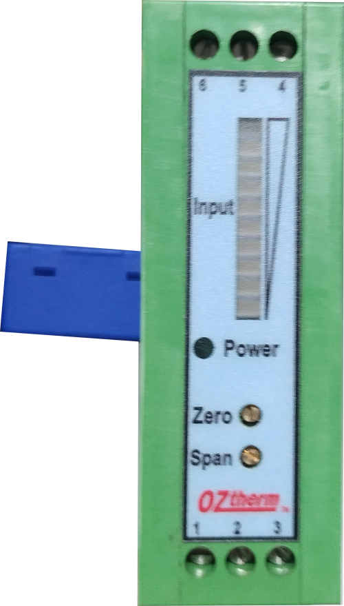
Image of F920 Series
For Transducers such as F92x series you will need a high current supply at least 20 Amp, and for Sensors with Aperture, you will need the ability to run multiple turns through the Hall Effect Sensor input to simulate larger currents. the largest current required for F920/F921 for example is 400 Amp AC or DC.
Example for 4-20mA Output F920 Transducer(C1 option):
1)Input the desired full scale input, for example for 25 Amp DC that will be running a calibrated source for 25 Amp DC through the sensor aperture.
2)In mA current range mode, connect the multimeter to the output terminals to check if you have 20mA on the output. if not you will need to adjust the snap POT clockwise until you see precisely 20mA
3)With no input current, check the output is 4mA, if not then fine adjust the zero POT to see precisely 4mA. Check the 25 Amp DC full scale input again.
Once these two inputs are showing the correct 4/120mA the Transducer is calibrated.
GT Series Transmitters
Process Level Transmitters
Process Level Transmitters & Meters with transmitters work in exactly the same way, except the input will generally be a similar process input for example 0-10V input for 4-20mA output.
New Digital F93x Transducers
Fastron is currently developing a new range of Current Transducers with Digital Zero and span Adjustment. There will be 3 models, and the Transducer will achieve an accuracy fo 0.2% in most current ranges and will utilise the latest generation of LEM Hall Effect Transducers and Microcontroller Technology.
The Current Range of Transducers in the market are limited to the lowest measurement ranges of 0-10 Amp for general use or 0-300mA for Earth Leakage. The new transducer range will be able to achieve a low measurement range of 0-2 Amp AC or DC, Full scale to allow for Railway LED monitoring applications.
In addition we will combine two solid state or relay based Alarm outputs which can double as a flasher and will aim to seek ARTC approval and expand to international markets.
The Preliminary Spec is outlined below.
F93x Current Transducer Conditioner Module (Preliminary)
The F93x series current transducer conditioning module is the next generation of current transducer from Fastron Electronics.
This series provides a non-contact/through hole DC current measurement using an internal Hall Effect transducer, the measurement range spans 300mA to 50A, depending on the model selected.
This module is housed in a 3 module wide DIN enclosure that allows installation in switchboards or stand alone operation.
- An LED display provides an immediate indication of the current in Amps
- Input Power supply 9-36VDC or 6-24VAC supply
- Current loop with 4-20mA range into a maximum load of 250 ohms
- Programming pushbuttons for configuration and test
- User settable Alarm(s) within current range of conditioner (Voltage free O/P)
- Unipolar/Bipolar output in either current loop or voltage outputs
- Programmable dead time for alarm outputs operation
Feature |
F930 (Basic) |
F931 (Middle) |
F932 (Top) |
|
Readout (3 digit) |
✔ |
✔ |
✔ |
|
4-20mA Process output |
✔ |
✔ |
✔ |
|
2-10V Process Output |
- |
✔ |
✔ |
|
1-5V Process Output |
- |
✔ |
✔ |
|
Unipolar Process Output |
✔ |
✔ |
✔ |
|
Bipolar Process Output (4-12-20mA or 1-3-5V or 2-6-10V) (+/-5V,+/-10V alternative) |
- |
✔ |
✔ |
|
Alarm 1 |
- |
✔ |
✔ |
|
Alarm 2 |
- |
- |
✔ |
|
Communications (Modbus) |
- |
- |
✔ |
|
Dead time delay 0.1 à 10S |
- |
- |
✔ |
Measurement Accuracy 0.2%
Operating Temperature range -10 to 70 Degrees C
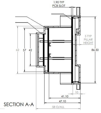
Enclosure dimensions (W x H x D) 54 x 58 x 90mm
Programming:
Features can be programmed using the three keys on the front of the module. No particular order at the moment.
Process output setting:
- Current loop or Voltage output
- Voltage 1 – 5V or 2 – 10V
- Unipolar / Bipolar output
Alarms:
- Set value (in actual current) alarm 1
- Set value (in actual current) alarm 2
- Dead time delay 0.1 – 10S
- Set process output to 4mA
- Set process output to 20mA
If the process output is set for voltage will be 1 – 2V or 5 – 10V
Useful information:
- Show model type
- Show Firmware version
- Segment test (Light all segments on the display)
Some info on DIN sizing
The width of devices that are mounted on a 35 mm "top hat" DIN rail generally use "modules" as a width unit, one module being 18 mm wide. For example, a small device (e.g. a circuit breaker) may have a width of 1 module (18 mm wide), while a larger device may have a width of 4 modules (4 * 18 = 72 mm wide).

For more Information feel free to contact our Technical Sales Team
, DIN Rail Mount kWh Meter, Single Phase, 240VAC aux, Class 1, 100Amp Direct Connect, w/ 2 x pulse outputs and RS485 Modbus RTU Comms, MID Approved")